
Welcome to Lesson 7! 🎉
レッスン7へようこそ!
In this lesson, you will learn about auxiliary electrical equipment – the comfort and convenience systems that make modern vehicles safe and enjoyable to drive.
このレッスンでは、現代の車両を安全で快適に運転するための補助電装品について学びます。
✓ Windshield wiper and washer systems
✓ Horn circuits and operation
✓ Power window systems
✓ Power door lock systems
✓ A/C electrical systems
✓ Accessory installation and wiring
This lesson takes approximately 5-6 hours to complete, including the quiz at the end.
Auxiliary Equipment Overview 🔧
補助電装品の概要
Auxiliary electrical equipment includes all electrical systems beyond the primary engine, charging, starting, and lighting systems.
補助電装品には、主要なエンジン、充電、始動、照明システム以外のすべての電気システムが含まれます。
• Safety systems: Wipers, horns, defoggers | 安全システム
• Comfort systems: Power windows, locks, mirrors | 快適システム
• Climate control: A/C, heating, ventilation | 空調制御
• Entertainment: Audio, navigation, displays | エンターテイメント
• Accessories: USB ports, power outlets, lighting | アクセサリー
• Total load: Can exceed 100+ amps in modern vehicles
• Fuse protection: Individual circuits protected
• Relay control: High-current devices use relays
• Body Control Module: Coordinates many functions
Windshield Wiper System 🌧️
ワイパーシステム
The windshield wiper system provides clear visibility in rain, snow, and other conditions that obstruct the driver’s view.
ワイパーシステムは、雨、雪、その他の視界を妨げる状況でクリアな視界を提供します。
• Wiper motor: Permanent magnet DC motor | ワイパーモーター
• Wiper linkage: Converts rotation to oscillation | リンケージ
• Wiper arms: Hold and position wiper blades | ワイパーアーム
• Wiper blades: Rubber strips that contact glass | ワイパーブレード
• Wiper switch: Controls speed and intermittent operation | スイッチ
• Two-speed operation: Low and high speed windings
• Park position: Motor stops at bottom of sweep
• Park switch: Internal switch controls park position
• Current draw: 3-6 amps typical
• Gear reduction: Worm gear provides torque
• Timer circuit: Controls delay between sweeps
• Variable delay: Adjustable interval (2-15 seconds)
• Rain sensor: Automatic speed adjustment
• Electronic module: Controls timing and speed
Wiper Circuit Operation 🔌
ワイパー回路の動作
• Fuse: Typically 15-25 amp protection
• Wiper switch: Multi-position rotary or stalk switch
• Relay: Controls high-current motor circuit
• Motor: Two or three brush DC motor
• Park switch: Cam-operated internal switch
• Low speed: Current through high resistance path
• High speed: Current through low resistance path
• Three-brush motor: Third brush for low speed
• Shunt wound motor: Field winding controls speed
• Switch off: Motor continues until park position
• Park switch: Opens when blades reach bottom
• Ground path: Maintained until park position
• Automatic park: Ensures blades don’t stop mid-sweep
Windshield Washer System 💦
ウォッシャーシステム
The washer system sprays cleaning fluid onto the windshield to help remove dirt, bugs, and debris.
ウォッシャーシステムは、汚れ、虫、ゴミを除去するためにクリーニング液をフロントガラスに噴射します。
• Washer reservoir: Holds washer fluid (2-4 liters)
• Washer pump: Electric centrifugal pump
• Washer nozzles: Spray jets on hood or wiper arms
• Washer hoses: Connect pump to nozzles
• Washer switch: Momentary contact switch
• Motor type: Small DC motor with impeller
• Current draw: 2-4 amps typical
• Pressure: 15-30 psi output
• Activation: Momentary switch operation
• Wiper coordination: Often activates wipers automatically
• Fan spray: Wide coverage pattern
• Jet spray: Concentrated stream
• Heated nozzles: Prevent freezing in cold weather
• Wiper-mounted: Spray directly at blade contact point
Horn System 📢
ホーンシステム
The horn is a safety device that alerts other drivers and pedestrians to the vehicle’s presence.
ホーンは、他の運転者や歩行者に車両の存在を知らせる安全装置です。
• Electromagnetic horn: Vibrating diaphragm type
• Air horn: Compressed air through trumpet
• Electronic horn: Solid-state sound generator
• Dual-tone: Two horns for fuller sound
• Electromagnet: Pulls diaphragm inward
• Contact points: Break circuit at full travel
• Spring return: Diaphragm returns to rest
• Vibration: Creates sound waves (300-500 Hz)
• Current draw: 4-6 amps per horn
• Horn button: Steering wheel mounted switch
• Horn relay: Controls high-current circuit
• Fuse: Typically 10-15 amp protection
• Clock spring: Allows steering wheel rotation
• Ground: Through horn body or wire
Power Window System 🪟
パワーウィンドウシステム
Power windows use electric motors to raise and lower door glass, providing convenience and safety features.
パワーウィンドウは電動モーターを使用してドアガラスを上下させ、利便性と安全機能を提供します。
• Window motor: Reversible DC motor | ワイパーモーター
• Window regulator: Converts rotation to linear motion | レギュレーター
• Window switch: DPDT reversing switch | スイッチ
• Master switch: Controls all windows from driver door | マスタースイッチ
• Window lockout: Disables passenger switches | ロックアウト
• Permanent magnet motor: Reversible by polarity change
• Gear reduction: Worm gear or spur gear
• Current draw: 10-20 amps under load
• Thermal protection: Circuit breaker prevents overheating
• Speed: Approximately 4-6 inches per second
• Cable type: Flexible cable with drum
• Scissor type: X-pattern linkage arms
• Single arm: One arm with sector gear
• Rack and pinion: Linear gear mechanism
Power Window Circuit 🔌
パワーウィンドウ回路
• DPDT switch: Double-pole double-throw for reversing
• Master/slave: Driver controls all, passengers control own
• Circuit breaker: Auto-resetting overcurrent protection
• Fuse: 20-30 amp main circuit protection
• Relay: May be used for high-current control
• Auto-reverse: Reverses if obstruction detected
• Anti-pinch: Current sensing detects resistance
• Express up/down: One-touch full travel
• Key-off operation: Works briefly after ignition off
• Child lockout: Disables rear window switches
⬇️ DOWN: Ground → Motor → +12V
• Slow operation: Worn motor brushes or dry tracks
• No operation: Check fuse, switch, motor
• Intermittent: Loose connections or worn switch
• Window falls: Broken regulator cable or clips
Power Door Lock System 🔐
パワードアロックシステム
Power door locks provide convenient locking and unlocking of all vehicle doors from a single switch or remote.
パワードアロックは、単一のスイッチまたはリモコンからすべての車両ドアの施錠・解錠を便利に行えます。
• DC motor actuator: Reversible motor with gear
• Solenoid actuator: Electromagnetic plunger
• Bi-directional solenoid: Two coils for lock/unlock
• Pneumatic: Air pressure operated (older vehicles)
• Motor type: Small reversible DC motor
• Gear reduction: Converts rotation to linear motion
• Travel: Approximately 10-15mm stroke
• Current draw: 3-5 amps momentary
• Speed: Locks in less than 1 second
• Transmitter: RF signal at 315 or 433 MHz
• Receiver: Antenna and control module
• Rolling code: Changes code each use for security
• Range: Typically 30-100 feet
• Functions: Lock, unlock, trunk, panic
Door Lock Features 🔒
ドアロック機能
• Speed-sensing lock: Locks at 15-20 km/h
• Shift-to-drive lock: Locks when put in gear
• Auto-unlock: Unlocks when shifted to park
• Collision unlock: Unlocks after airbag deployment
• Walk-away lock: Locks when key fob moves away
• Passive entry: Unlock by touching door handle
• Push-button start: No key insertion needed
• Proximity detection: Senses key within range
• LF/RF communication: Two-way signal exchange
• Backup key: Mechanical key hidden in fob
Power Mirror System 🪞
パワーミラーシステム
Power mirrors allow the driver to adjust exterior mirror position electrically for optimal rear visibility.
パワーミラーは、最適な後方視界のために外部ミラーの位置を電気的に調整できます。
• Mirror motors: Two DC motors per mirror (up/down, left/right)
• Mirror switch: Joystick or rocker type
• L/R selector: Chooses which mirror to adjust
• Mirror glass: Mounted on pivot mechanism
• Housing: Contains motors and heating element
• Reversible motors: Change direction by polarity
• Gear reduction: Worm gear for precise control
• Current draw: 1-2 amps per motor
• Travel limits: Mechanical stops prevent over-travel
• Memory function: Stores positions for drivers
• Heated mirrors: Defrost/defog in cold weather
• Auto-dimming: Reduces glare from headlights
• Power folding: Folds for parking or car wash
• Blind spot indicators: Warning lights in mirror
• Turn signal: Integrated LED indicators
A/C Electrical System ❄️
エアコン電気システム
The air conditioning electrical system controls the compressor, fans, and sensors to maintain cabin temperature.
エアコン電気システムは、車内温度を維持するためにコンプレッサー、ファン、センサーを制御します。
• Compressor clutch: Electromagnetic clutch engages compressor
• Condenser fan: Cools refrigerant in condenser
• Blower motor: Circulates air through cabin
• Control panel: Temperature and fan speed controls
• A/C relay: Controls compressor clutch circuit
• Evaporator temperature: Prevents icing (thermistor)
• Ambient temperature: Outside air temperature
• In-car temperature: Cabin temperature sensor
• Sunload sensor: Measures solar heat load
• Pressure switches: High and low pressure protection
• Electromagnetic coil: Creates magnetic field
• Clutch plate: Engages to drive compressor
• Air gap: 0.4-0.8mm typical clearance
• Current draw: 3-5 amps when engaged
• Cycling: On/off to maintain temperature
Blower Motor System 💨
ブロワーモーターシステム
The blower motor circulates air through the HVAC system to heat or cool the vehicle cabin.
ブロワーモーターは、車内を暖房または冷房するためにHVACシステムを通じて空気を循環させます。
• DC motor: Permanent magnet type
• Squirrel cage fan: Centrifugal blower wheel
• Speed control: Resistor or electronic module
• Housing: Mounted in HVAC case
• Current draw: 5-20 amps depending on speed
• Resistor pack: Series resistors reduce voltage
• Transistor module: Electronic speed control
• PWM control: Pulse width modulation for efficiency
• Automatic climate: Computer-controlled speed
Resistors drop voltage to reduce motor speed
• No operation: Check fuse, relay, motor
• Only high speed: Failed resistor pack
• Noisy operation: Worn bearings or debris
• Intermittent: Bad connection or worn brushes
Rear Window Defogger 🔥
リアウィンドウデフォッガー
The rear window defogger uses heating elements embedded in the glass to clear fog and ice.
リアウィンドウデフォッガーは、ガラスに埋め込まれた加熱素子を使用して曇りや氷を除去します。
• Grid lines: Thin conductive strips on glass
• Bus bars: Vertical bars connect grid lines
• Relay: Controls high-current circuit
• Timer: Auto-shutoff after 10-15 minutes
• Indicator light: Shows system is active
• Voltage: 12V applied across bus bars
• Current draw: 15-25 amps typical
• Power: 180-300 watts total
• Grid resistance: 0.5-2 ohms per line
• Operating time: Clears in 5-10 minutes
• Damage causes: Scratches, impacts, age
• Testing: Voltmeter along grid line
• Repair kits: Conductive paint or tape
• Application: Clean, apply, cure with heat
Power Seat System 💺
パワーシートシステム
Power seats use multiple electric motors to adjust seat position for driver comfort and safety.
パワーシートは複数の電動モーターを使用して、運転者の快適性と安全性のためにシート位置を調整します。
• Fore/aft motor: Moves seat forward/backward
• Height motor: Raises/lowers seat
• Recline motor: Adjusts seatback angle
• Lumbar motor: Adjusts lower back support
• Tilt motor: Adjusts seat cushion angle
• Motor type: Reversible DC motors
• Current draw: 10-20 amps per motor
• Circuit protection: 30 amp fuse or breaker
• Switch type: Multi-position rocker switches
• Memory function: Stores preferred positions
• Heating elements: Resistance wire in cushion/back
• Thermostat: Maintains set temperature
• Control: High/low or variable settings
• Current draw: 3-5 amps per seat
• Auto-shutoff: Timer prevents overheating
Accessory Installation 🔌
アクセサリー取付
Proper accessory installation requires understanding of vehicle electrical systems and safe wiring practices.
適切なアクセサリー取付には、車両電気システムと安全な配線方法の理解が必要です。
• Audio systems: Amplifiers, speakers, subwoofers
• Lighting: LED strips, fog lights, work lights
• USB chargers: Phone and device charging
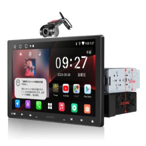
• Dash cameras: Front and rear recording
• Navigation: GPS and display systems
• Wire gauge: Match to current requirements
• Fuse protection: Always fuse positive wire
• Grounding: Solid connection to chassis
• Routing: Avoid heat sources and moving parts
• Connectors: Use proper automotive connectors
• Up to 5 amps: 18 AWG minimum
• 5-10 amps: 16 AWG minimum
• 10-15 amps: 14 AWG minimum
• 15-20 amps: 12 AWG minimum
• 20-30 amps: 10 AWG minimum
Relay Installation 📦
リレー取付
Relays are essential for controlling high-current accessories with low-current switches.
リレーは、低電流スイッチで高電流アクセサリーを制御するために不可欠です。
• Terminal 30: Constant battery power input
• Terminal 87: Output to accessory (normally open)
• Terminal 87a: Output (normally closed)
• Terminal 85: Coil ground
• Terminal 86: Coil positive (switched)
1. Connect fused battery power to terminal 30
2. Connect accessory positive to terminal 87
3. Connect switch output to terminal 86
4. Connect terminal 85 to ground
5. Ground accessory negative to chassis
🔘 Switch → [86] 📦 [85] → ⏚ Ground
• Fuse location: As close to battery as possible
• Relay mounting: Secure in dry location
• Wire routing: Use grommets through panels
• Testing: Verify operation before final assembly
Body Control Module 🧠
ボディコントロールモジュール
The Body Control Module (BCM) is a central computer that controls and coordinates many auxiliary electrical functions.
ボディコントロールモジュール(BCM)は、多くの補助電気機能を制御・調整する中央コンピューターです。
• Lighting control: Interior and exterior lights
• Power accessories: Windows, locks, mirrors
• Security: Alarm, immobilizer, keyless entry
• Convenience: Auto-lock, delayed lighting
• Communication: CAN bus interface
• CAN bus: High-speed data communication
• LIN bus: Low-speed accessory control
• Module coordination: Shares data with ECU, TCM
• Diagnostic access: OBD-II communication
• Software updates: Programmable functions
• DTC storage: Records fault codes
• Input/output testing: Actuator and sensor tests
• Configuration: Enable/disable features
• Module programming: Software updates
• Security access: May require authorization
Troubleshooting Auxiliary Systems 🔧
補助システムのトラブルシューティング
1. Verify complaint: Confirm the problem
2. Check basics: Fuses, grounds, connections
3. Scan for codes: BCM and related modules
4. Test components: Switches, motors, relays
5. Check wiring: Continuity and voltage drops
6. Repair and verify: Fix and confirm operation
• Voltage test: Check power at component
• Ground test: Verify good ground connection
• Continuity test: Check wire integrity
• Current draw: Measure motor amperage
• Resistance test: Check switches and motors
• Purpose: Find high-resistance connections
• Method: Measure voltage across connections under load
• Acceptable: Less than 0.2V on power side
• Acceptable: Less than 0.1V on ground side
• High drop: Indicates poor connection
• Connectors: Corrosion, loose pins
• Switches: Worn contacts, broken
• Motors: Worn brushes, seized bearings
• Wiring: Chafed, broken, shorted
• Grounds: Corroded, loose mounting
Component Testing 🔬
部品テスト
• Power test: Apply 12V directly to motor
• Polarity test: Reverse leads for direction change
• Current draw: Should match specifications
• No-load speed: Motor should spin freely
• Stall current: Maximum when motor blocked
• Continuity: Check each position
• Resistance: Should be near zero when closed
• Infinite: When switch is open
• Intermittent: Wiggle while testing
• Contact condition: Look for burning or pitting
• Coil resistance: Typically 50-100 ohms
• Contact continuity: Check NO and NC contacts
• Activation test: Apply 12V to coil terminals
• Click test: Should hear relay click
• Contact resistance: Should be less than 0.5 ohms
Japanese Regulations 🇯🇵
日本の規制
Japan has specific regulations governing auxiliary electrical equipment for vehicle safety and compliance.
日本には、車両の安全性とコンプライアンスのための補助電装品を規制する特定の規則があります。
• Wipers: Must have at least two speeds
• Washer: Must be functional
• Horn: Must produce 93-112 dB at 2m
• Defogger: Required for rear window
• Mirrors: Must be adjustable
• Wipers: Must operate correctly on all speeds
• Washer: Must spray adequately
• Horn: Must sound properly
• Windows: Must open and close fully
• Defogger: Must heat rear window
• Lighting: Color and brightness restrictions
• Audio: Noise level limits
• Window tint: Minimum 70% VLT front windows
• Modifications: Must not affect safety systems
• EMI: Must not interfere with other electronics
Lesson Summary 📋
レッスンのまとめ
Congratulations! You’ve learned the essential concepts of auxiliary electrical equipment.
おめでとうございます!補助電装品の重要な概念を学びました。
• Wiper systems: DC motors with park circuits
• Horns: Electromagnetic vibrating devices (4-6A)
• Power windows: Reversible motors with DPDT switches
• Door locks: Motor or solenoid actuators
• A/C electrical: Compressor clutch and blower motor
• Accessory installation: Correct wire gauge and fusing
• BCM: Coordinates many auxiliary functions
• Wiper motor: 3-6 amps
• Horn: 4-6 amps, 93-112 dB
• Power window motor: 10-20 amps
• Blower motor: 5-20 amps
• Defogger: 15-25 amps
• Relay coil: 50-100 ohms
Now it’s time to test your knowledge with a 10-question quiz. You need 70% (7/10) to pass. Good luck!
10問のクイズで知識をテストしましょう。合格には70%(7問正解)が必要です。頑張ってください!
📝 Lesson 7 Quiz
レッスン7クイズ
Test your knowledge with 10 multiple-choice questions.
10問の多肢選択式問題で知識をテストします。
• 10 multiple-choice questions
• Passing score: 70% (7/10 correct)
• You can review your answers after completion
• Take your time and read carefully
Click “Next” to begin the quiz. Good luck!
「次へ」をクリックしてクイズを開始します。頑張ってください!
問題1: ワイパーをオフにしたときにブレードがパーク位置に戻ることを保証する部品は?
正解はB) パークスイッチです。パークスイッチはカム作動式の内部スイッチで、ブレードがパーク位置に達するまでモーターへの接地を維持します。
問題2: 自動車ホーンの典型的な電流消費は?
正解はB) 4-6アンペアです。典型的な自動車用電磁ホーンは作動時にホーン1つあたり4-6アンペアを消費します。
問題3: パワーウィンドウモーターを逆転させるために使用されるスイッチの種類は?
正解はC) DPDTです。双極双投スイッチはモーターへの極性を反転させ、回転方向を変えます。
問題4: リモートキーレスエントリーシステムで使用される典型的な周波数は?
正解はB) 315または433 MHzです。リモートキーレスエントリーは通常315 MHz(北米/日本)または433 MHz(欧州)のRF信号を使用します。
問題5: エアコンコンプレッサーの作動を制御するものは?
正解はB) 電磁クラッチです。電磁クラッチはコンプレッサーをエンジン駆動ベルトに接続・切断します。
問題6: ブロワーモーターが高速でのみ動作する場合、最も可能性の高い原因は?
正解はB) 抵抗器パック故障です。抵抗器パックは低速用に電圧を下げます。故障すると、高速(抵抗器をバイパス)のみ動作します。
問題7: リアウィンドウデフォッガーの典型的な電流消費は?
正解はB) 15-25アンペアです。リアウィンドウデフォッガーは通常180-300ワットの熱を発生させるために15-25アンペアを消費します。
問題8: 常時バッテリー電源を受けるリレー端子は?
正解はA) 端子30です。端子30は常時バッテリー電圧を受ける電源入力端子です。
問題9: 自動車用リレーの典型的なコイル抵抗は?
正解はB) 50-100オームです。自動車用リレーコイルは通常50-100オームの抵抗を持ちます。
問題10: 自動車電気システムにおけるBCMの意味は?
正解はA) ボディコントロールモジュールです。BCMは多くの補助電気機能を制御・調整する中央コンピューターです。
結果を計算中…
You’ve completed Lesson 7! Continue with more lessons in Module 5 or review your answers below.
Lesson 7 Complete! 🏆
レッスン7完了!
✓ Windshield wiper and washer systems
✓ Horn circuits and operation
✓ Power window systems and circuits
✓ Power door lock and keyless entry
✓ Power mirror systems
✓ A/C electrical components
✓ Blower motor and defogger systems
✓ Accessory installation and relay wiring
✓ Body Control Module functions
✓ Troubleshooting auxiliary systems
Excellent work! You have completed Lesson 7: Auxiliary Electrical Equipment!
Continue with the remaining lessons in Module 5 to master electrical systems!
素晴らしい!レッスン7:補助電装品を完了しました!
モジュール5の残りのレッスンを続けて、電気システムをマスターしましょう!